Product description
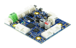
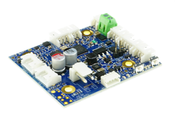
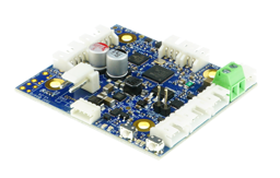
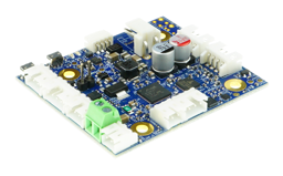
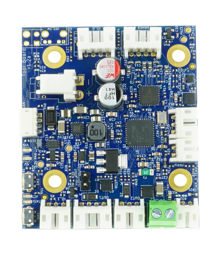
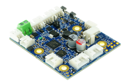
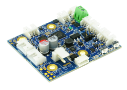
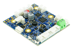
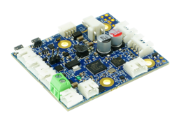
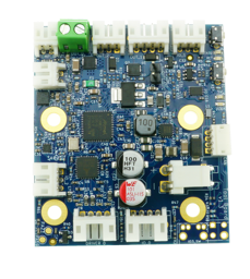
The Duet 3 Tool board is a CAN-FD connected expansion board for the Duet 3 Mainboard that is designed to provide complete control for a direct drive extruder, associated fans, filament sensor and probe. The mounting holes and connector locations match an e3d Hemera (v1.2a) or Hemera XS(v1.3) , however it can be used with other direct drive extruders with suitable brackets. The stepper motor, heater, temperature sensor, fans and optionally Z probe and filament monitor all connect to the Duet 3 Tool board, leaving only CAN-FD and power wires to run back to the Duet 3 Mainboard or Tool Distribution Board.
There are two current versions.
- V1.2a – Hole spacing for the E3D Hemera:

- V1.3 – Hole spacing for the E3D Hemera XS (11mm closer together):

The overall board dimensions are unchanged.
The connector pack includes the following:
- JST PH housings + crimps for the Driver 0, OUT1, 2, IO 0,1,2 and Temp connectors
- 4-way JST ZH tail 100mm+ with plug (CAN in)
- 2-way JST VH housing & crimps
- White single ferrules for heater screw terminals
FEATURES
| Processor | ARM Cortex M0+ processor running at 48MHz |
| Connectivity | CAN-FD interconnect to main controller board and other Toolboards or expansion boards |
| Stepper Driver | One TMC2209 stepper driver with stall detection and stealthChop. Maximum output current 1.6A peak, 1.1A RMS |
| High current outputs | 1 x 5A rated output for the hot-end heater (60W at 12V VIN, 120W at 24V VIN, 24V recommended) |
| Medium current outputs | One 3-wire fan output (also accepts 2-wire fan); one 4-wire fan output (also accepts 2-wire fan) |
| IO | Two thermistor or PT1000 inputs. One uses a 16-bit ADC for high resolution reading of PT1000 sensors; one 3-pin filament monitor connector; one Z-probe connector; one footprint to mount a ultra subminiture switch; two push buttons and indication LEDs; 12 to 32V power input; On-board 12V, 5V and 3.3V regulators |
| Firmware | RepRapFirmware 3.x (3.4 or later recommended for using the accelerometer with input shaping) |
Documentation
| Hardware overview | GO TO DOCUMENTATION > |
RELATED PRODUCTS
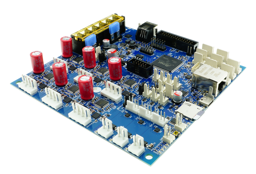
An advanced, high power controller that features 6x 6.3A stepper drivers, 4 high current heaters, 6 fans and more
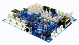
An advanced, high power controller that features support for 6 external stepper motor drivers, along with similar outputs and IO as the Duet 3 Mainboard 6HC.
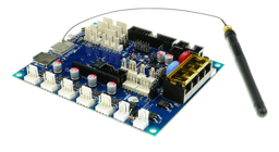
An advanced, mid range controller that features 5x 2A stepper drivers, 3 high current heaters, 4 fans and more.
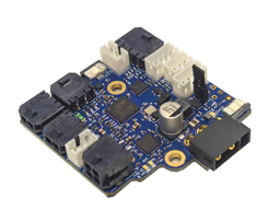
The Duet 3 Roto Toolboard is designed to integrate easily with the E3D Revo Roto extruder and the Revo hotend heaters and temperature sensors.
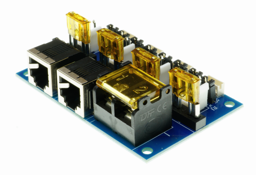
This board allows for the connection of up to 4 Duet 3 Toolboards to the Duet 3 Mainboard at one time, greatly simplifying the CAN-FD bus and power wiring.

